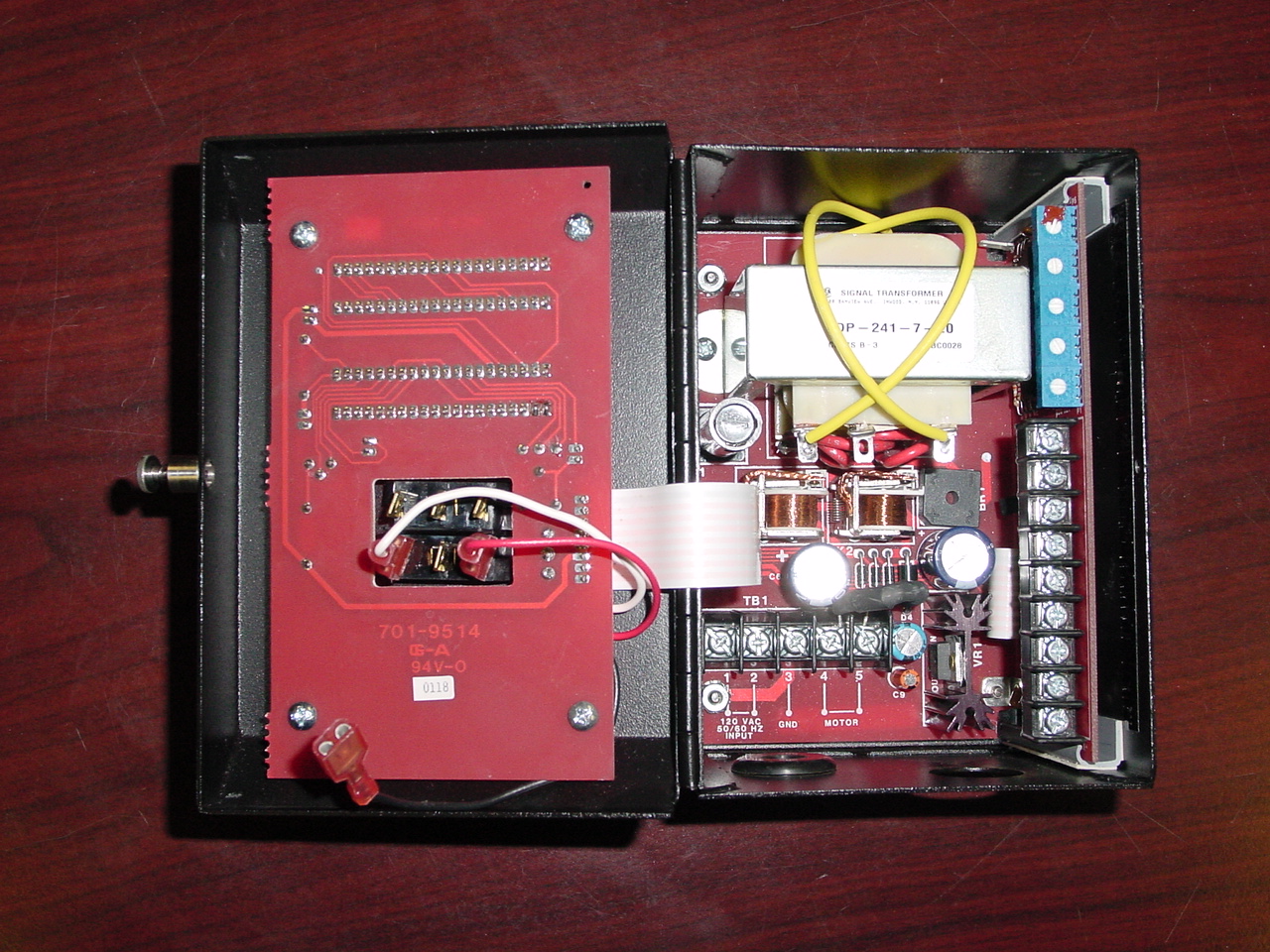
Given all the trouble with fused relays in the JT4 controller we asked Joe Beaufait to make wiring harnesses with connectors on them that would allow us to swap controllers rapidly if needed. We have two of these harnesses: one for the in-use controller and one for a spare. Here is the wiring layout to install the harnesses in a controller (see Figure 1 for a picture of the inside of the controller).
| Terminal Strip | Pin | Wire Color | Connector Pin | Control System Wire |
|---|---|---|---|---|
| TB1 | 1 | Brown | A | 11290 |
| TB1 | 2 | Red | B | 11252 |
| TB1 | 3 | Orange | C | Green (GND) |
| TB1 | 4 | Yellow | D | 35370 |
| TB1 | 5 | Green | E | 35371 |
| See Below | Violet | F | 35340 | |
| See Below | Blue | G | 35341 | |
TB1 runs horizontally along the bottom of the box and is numbered from left to right. The violet wire with the male stake-on connector on wiring harness 1 connects to a black wire with a female stake-on connector dangling from behind the circuit board inside the front lid of the controller. The blue wire with the female stake-on connector plugs onto the middle connector (between the red and white wires) on the bottom row of the set of male stake-ons protruding through the circuit board inside the front lid of the controller.
| Terminal Strip | Pin | Wire Color | Connector Pin | Control System Wire |
|---|---|---|---|---|
| TB2 | 1 | Brown | A | 35374 |
| TB2 | 2 | Red | B | 35373 |
| TB2 | 3 | Orange | C | 35372 |
| TB2 | 4 | Yellow | D | SHLD |
| TB2 | 5 | Green | E | 04CH8+ |
| TB2 | 6 | Blue | F | 04CH8- |
| TB2 | 7 | Violet | G | 35344 |
| TB2 | 8 | Grey | H | 35343 |
| TB2 | 9 | White | K (?) | 35342 |
TB2 runs vertically along the right side of the box and is numbered from bottom to top.
A